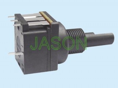
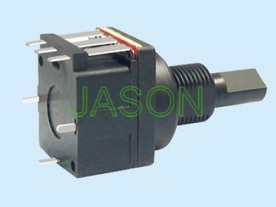
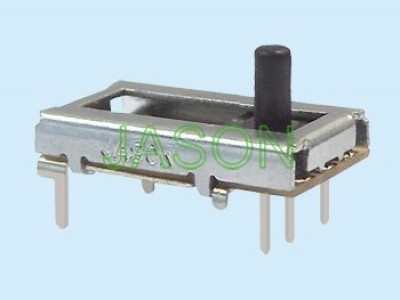
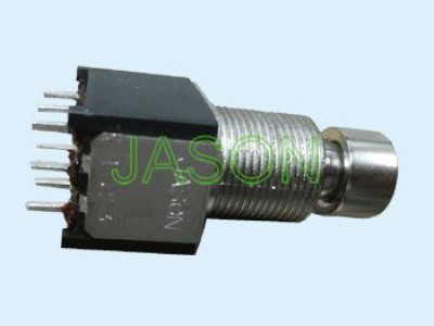
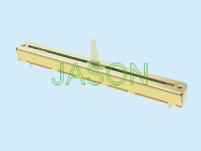
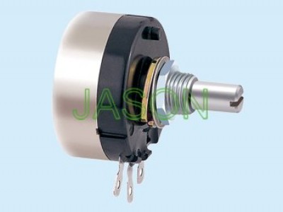
The adjustable potentiometer can generally change the position of the movable contact point in the resistor body by manually adjusting the shaft. However, between the movable contact point and the fixed contact point, there is an object that is related to the position of the movable contact point. Voltage. Due to the small size of the adjustable potentiometer, there are usually many precautions that need to be paid attention to during installation. If the operation is not performed properly, it will undoubtedly lead to faults. So I think everyone needs to know the basic knowledge about the details of adjustable potentiometer welding, and then I will give you a detailed introduction to the details of adjustable potentiometer welding.
Adjustable potentiometer welding key points
Key points of electric welding
Generally, during the resistor welding process, when the spot welding of each pin has not solidified, please do not move the spot welding, because even small shocks and vibrations can easily deform the spot welding and cause damage. causing a virtual connection situation. Therefore, generally after the soldering of the resistor pins is completed, you can blow air through your mouth to check the spot welding area or use a hair dryer to quickly reduce the time for the spot welding to condense.
Key points two of electric welding
Secondly, when welding the resistor, we must pay attention to the welding time to be controlled well and not too long. Generally, in the electric welding of circuit boards, the electric welding time is generally 2 to 3 seconds. Because the resistor welding time is too long, the flux in the welding material will completely evaporate, losing the welding effect, causing the spot welding surface to oxidize, resulting in defects such as the spot welding surface being rough, burrs, blackening, or fluidity. Therefore, the resistor may be soldered directly.
Three key points of electric welding
There are also resistors that require cleaning of the soldering iron head before and during welding, because the plugged-in soldering iron head will be in a high temperature state for a long time. If there is too much dirt or dirt, This situation may cause the surface of the resistor to be easily oxidized or set on fire, which will also affect the heat transfer performance of the soldering iron tip and affect the welding quality.
Key points four of electric welding
The amount of tin welded on each spot of the resistor should be appropriate. Generally, more tin is not better for spot welding. If too much solder wire is added, it is easy to cause the solder wires to be deposited together and unable to be melted, thus causing the problem. This causes unstable resistor welding and false welding. Therefore, if the amount of tin applied at one time is insufficient, it can be repaired by welding again. Avoid adding too much, which will waste welding materials and, secondly, harm the welding operation.
Five key points of electric welding
During the actual welding operation of the adjustable potentiometer, please properly dispose of the unnecessary tin spilled on the pins and PCB circuit boards, otherwise it cannot be removed after condensation, which will in turn affect the Resistor Characteristics Applications.
This is the basic knowledge about the key points of welding the left and right adjustable potentiometers. Looking back, I have explained to you the pin definition and wiring method of the patch type adjustable potentiometer. So in general, I hope that the knowledge structure diagram such as the key points of adjustable potentiometer welding will be helpful to everyone. It also reminds you of the key points of some common problems in the installation or use of resistors. Points cannot be ignored, otherwise the resistor will be abnormal due to neglect of some subtle details, and it may also cause damage.


